


语言


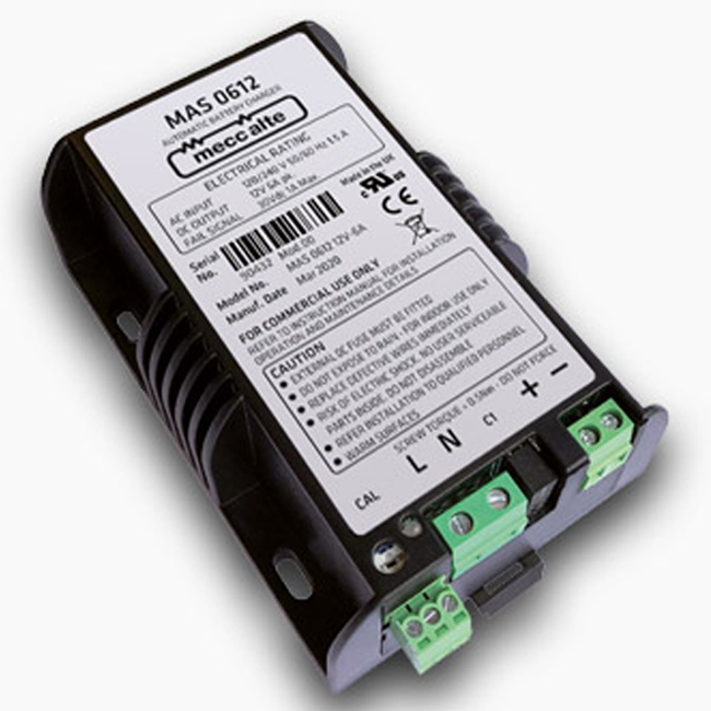
Product Features:
AC INPUT RATING
Voltage range :90 - 264V
Frequency :47 - 63Hz
Input current :1.5A max
DC OUTPUT RATING
Voltage & current :12V 6.0Apk (12V model)
24V 3.0Apk (24V model)
Ripple & noise :<0.5%
Line regulation :±1.0%
Load regulation :±1.0%
Efficiency Up to :90%
OPERATING CONDITIONS
Operating temperature :-10 to +50 ℃
Storage temperature :-20 to +85 ℃
CONNECTION
Rising clamp terminals.
Maximum cable cross-section = 2.5mm2
ENCLOSURE
High impact ABS plastic, black finish
WEIGHT
400 grams

IMPORTANT
• This device is to be installed and operated by skilled and qualified personnel ONLY and in compliance with current standards to avoid damage and safety hazards.
• For use within specified parameters only.
• Ensure adequate air-flow over all sides of case.
• Do not install in proximity of explosive gasses or flammable materials.
• Isolate the AC input supply and battery before any connection or disconnection to the units terminals.
INSTALLATION
The charger should only be installed in electrical panels with covers or doors and adequate ventilation should be considered.
Mount the unit on a flat heat conductive surface.
The charger can be mounted on symmetrical 35 x 7.5mm DIN rail or fixed using 2 No. (diagonally) or 4 No. M4 screws through the preformed holes in the mounting flanges.
Leave at least 15mm of space on all sides for adequate heat dispersion and free air convection.
CONNECTION
Ensure that the AC supply and battery are isolated before connection. It is good practice to install the charger close to the battery and to use conductors of sufficient cross-section to minimise voltage drops (thus maximising the battery charge).
The AC input should be protected by an MCB or fuse.
A 10A HRC DC output fuse should be fitted for battery protection.
OPERATION
Default Mode (3 Stage Charger With Battery Detection):
The MAS 06 12 is designed for charging most battery types. The default configuration is 3 stage (bulk / absorb / float). When a battery is connected the chargers output switches on to charge the battery.
Removal of the battery and all connected load switches the output off.
The charger is protected against reverse battery polarity in this mode.
PSU Mode (PSU / 2 Stage Charger Without Battery Detection) :
Linking pins 7 and 8 of the signals connector ‘C1’ forces the charger into PSU mode (constant current / constant voltage output) where the chargers output is always on.
The charger is not protected against reverse battery polarity in this mode.
OUTPUT VOLTAGE CALIBRATION
The output float voltage is factory preset to 13.8V (12V units) or 27.6V (24V units).
The operator MUST ensure that the chargers output voltage is set in accordance with the battery manufacturers recommendations.
To set the output voltage:
• Disconnect the battery and all loads connected to the output terminals.
• Attach a calibrated DVM to the +/- output terminals.
• Turn the ‘CAL’ pot fully anti-clockwise (minimum). The LED is off.
• When the LED flashes Green / Red adjust the ‘CAL’ pot to the desired output voltage, displayed on the DVM.
• When the LED stops flashing Green / Red the unit is calibrated.

如果您有任何问题,请联系我们咨询


东莞市南城街道新基路5号新基地科技产业园A座227-228


Copyright Notice © 2023 Wespcgroup.com All rights reserved
免责声明:本网站的布局、设计和编辑版权归WESPC所有。WESPC销售新的剩余产品和使用过的备件,并开发购买此类产品的渠道。
本网站未经任何制造商或列出的商品名批准或批准。除非另有规定,WESPC不是授权经销商、附属公司或
所列制造商的代表。此处出现的指定商标、品牌名称和品牌均为其各自所有者的财产。网站上使用的所有产品都描述、描述或销售带有
这些名称、商标、品牌和徽标仅用于识别目的,并不意味着它们与任何权利持有人有任何从属关系或获得任何权利。某人的授权。


 0086-0769-23380715
 0086-13265293976
 pfwey@wespcgroup.com
 www.wespcgroup.com
